
My other posts are more about me rambling about stuff, but I’m hoping for this one I can help someone who wants to achieve a similar modification.
THE RAMBLE
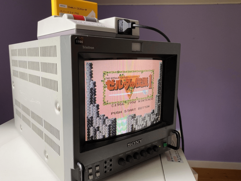
I’ve been wanting to setup my childhood N64 to take another crack at finishing the Perfect Dark campaign on hard difficulty. I setup my flat-screen and it sucked. The latency was horrible, it looked like garbage, and it just felt wrong. As a lover of old tech I felt like I was doing myself a disservice. I started looking at old quality CRTs and the SONY PVC monitors caught my eye. Partially because of how cool they were but also why they were so god damn expensive. Apparently they are awesome or something but honestly I just thought their aesthetic perfectly matched my tastes.
Now I absolutely couldn’t afford them, and I really try to avoid meddling in territories even near “collectors”, but I just loved these things so much I couldn’t resist. So to be completely not within reason, but reasonable, I settled for a JVC brand monitor of the same type. Some guy was selling a 14in one for a decent price in Quebec and I snagged it. The problem leading to this TV and many like it in the professional monitor scene, is that they do not use standard consumer video ports. Although many use the same technology in behind the ports, the connector itself is non-standard, and thus the conversion part of the post begins.
THE MOD
In General, be careful working with CRTs. I haven’t done it a lot, but I do know this is a situation where you want to listen to the warning labels. Absolutely unplug the device, but just know that there are massive capacitors in these devices that can really pack a punch. It takes some serious magnetic fields to bend something travelling at the speed of light.
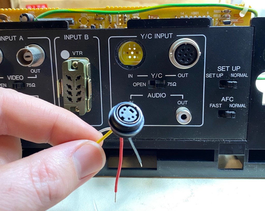
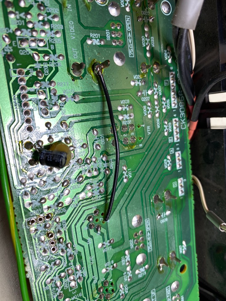
Below is a picture of the rear panel of the JVC TM-1400.

Using the following site as a great starting point, I started the mod. https://crtdatabase.com/crts/jvc/jvc-tm-1400su
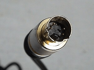
The “Y/C INPUT” (Red) section of the panel is where we will be focusing. That big ol’ 7-Pin Military style Y/C input connector is non-standard. You might find them on Digi-Key or elsewhere, but I really hate messing with that stuff. If you don’t have the right part number and the exact keyways etc., I find sourcing the correct one becomes a nightmare real quick. If you make a cable adapter using this connector there’s also potential issues with signal impedance related stuff so there’s some levels to that game. Because of that, instead of doing the “easy” thing and just making the adapter, I decided I wanted to convert to a standard S-Video connector directly on the rear panel.
PREP
I purchased the following connector: https://www.digikey.ca/en/products/detail/same-sky-formerly-cui-devices/MD-40CV/352861
This connector is not perfect because the threads were not long enough to reliably fix the connector to the panel. I had to basically thread the nut a half rotation on and then epoxy it all together. I’d rather not permanently fix a connector to the back, but it definitely would have fallen off the panel with a few uses.
The key word to find these was “Mini din”. If you’re someone not used to sourcing connectors, finding the manufacturer keys words is not as obvious as it seems for connectors like these. Usually the consumer naming conventions for them do not apply to the connectors themselves. If you can find a 4-pin S-Video connector with a slightly longer thread, and a conductive shell, then you won’t have to jump the shield with a long black wire to the back of the PCB like I did later in the post.
I use 22ga solid core wire for basically all of my projects. I just have 4 colours, but the multi-coloured packs seem pretty sweet and I will probably pick this up when I start getting low: https://www.adafruit.com/product/1311
Disassembly
First thing was taking the back panel off. There’s obvious screws on the outside of the case with arrows showing you the screws required to pull off the main casing. Then, below are the screws required to pull the main board away from the chassis. These arrows are in Red in the image below.
Once the screws are out, you’ll need to slightly pry up on two tabs located here, once those unlatch from the “MAIN PB” board, the rear panel should come free. These tabs located in the holes with the Orange arrows below.
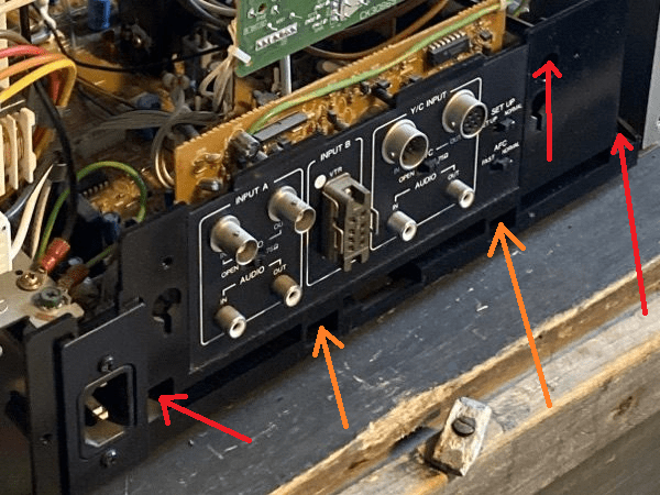
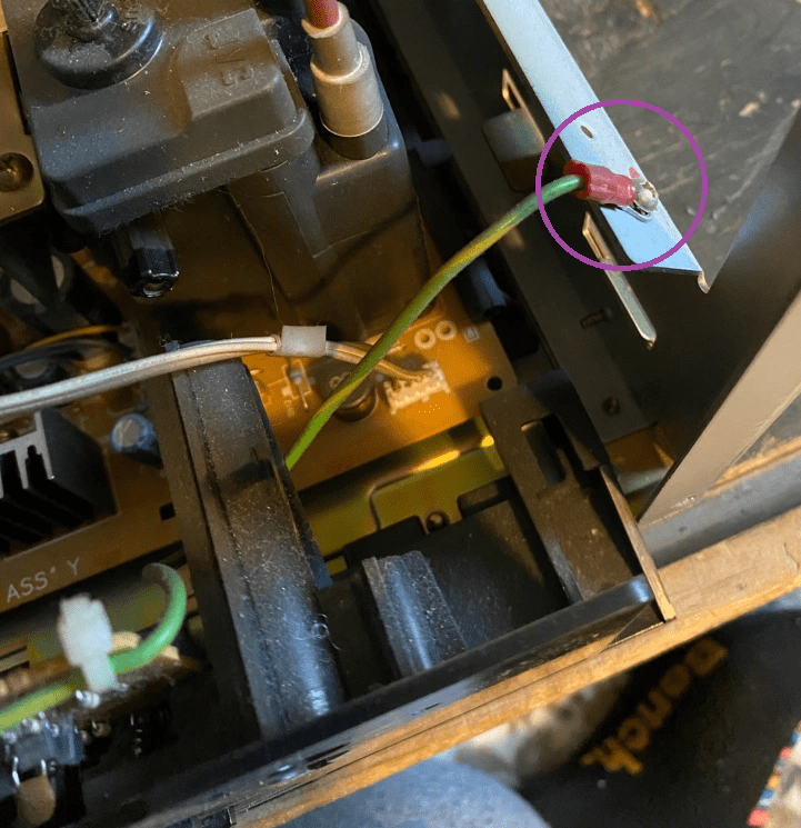
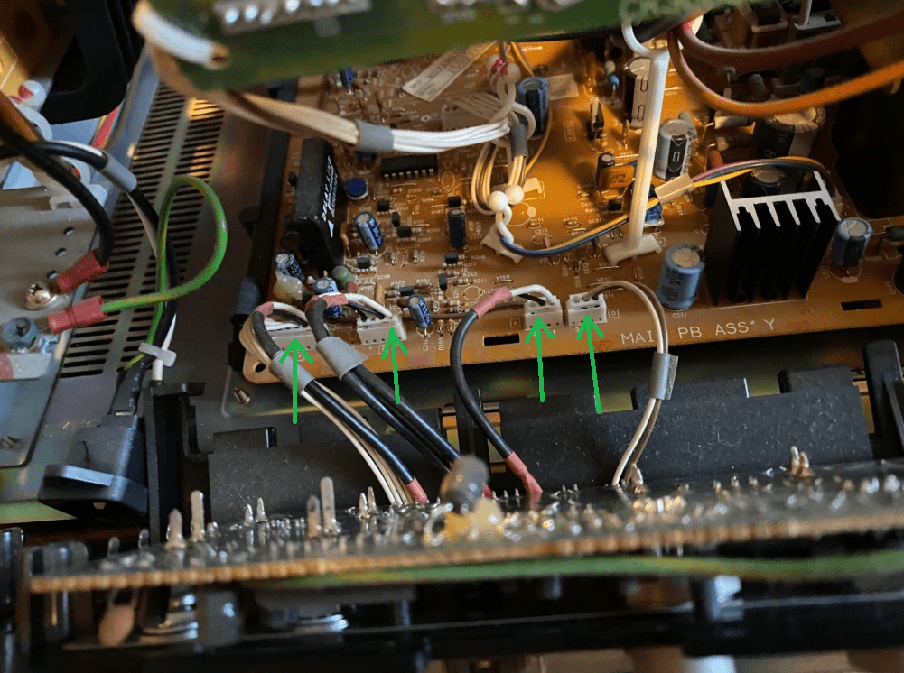
After unscrewing the ground wire (Purple), unscrew the AC plug from the rear panel (you will need pliers to hold the nuts in behind), and unplug the rear panel from the “Main PB” Board as shown in the picture below (4 green arrows), the rear panel should completely detach from the TV.
Removal of Connector
Here’s where things get a bit messy. They manufactured this board by installing all the connectors to the rear panel first, and then they soldered the rest of the board to each of those connectors. This means the board is basically never coming free from the plastic without a disaster unfolding in some way, shape, or form. To remove this connector, we need to remove the nut from the connector, then de-solder the connector from the board, and at that point it should come free.
The next problem with this is that there are two transistors precariously close to the connector. One wrong move and you are back to Digi-Key looking for equivalent transistors to transistors selected in the 90s now laying pieces in your tears on your workbench.
To keep your eyes dry, removing these two transistors temporarily is highly recommended. Once they are removed, and the post marked in the image below is removed, accessing the connector nut will be much easier. These transistors do not have the same part number, so make sure they go back on the right way when you are done.
Unscrewing of the connector will need some of the right tools, and some careful attention to the nearby components. You’ll need to lightly grab the outside of the connector while loosening the nut with another pair of pliers. If you can find a small pair of pliers with coarse teeth to grab onto the nut, then this should be easy. I lightly clamped a pair of small vice grips on the bayonets on the outside part of the connector, then carefully loosened the nut. You will need to break some thread-locker on the nut so it will take some force.
Soldering the New Connector
The soldering of the new S-Video connector can be done differently depending on the type of connector you use. If the S-Video connector you use has the exact same 7-pin layout as the original connector, then methods like the one mentioned in the following link is probably best. https://crtdatabase.com/crts/jvc/jvc-tm-1400su
I do prefer my connector style since your connector options open up, and you can avoid cutting traces. Not that cutting traces is a skill one should be afraid of, but ya know not all things need to become barbaric.
The table below is my wiring table based on two photos with attached sources.
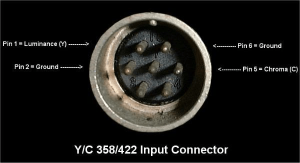
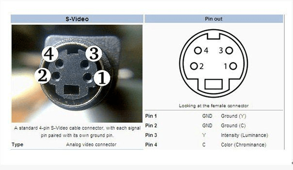
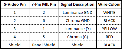
In general making tables like this will save you. Numbers and pinouts and flipped connectors can get jumbled in your brain very quick and that’s how the magic smoke gets let out. Always have connector images with their pin numbers, and your wiring table within reach. Also be careful when looking at connector images on the internet. Sometimes its hard to tell if its the male or female diagram and often is not made clear unless its an actual photo with the pin labels.
Below is a picture of my note book. Sometimes I like to take all the information and put it down on one page with some crude, yet unmistakable hand drawings of the connectors. Its messy but it works.

First I cut small lengths of wire and stripped their ends. I always tin each pin and wire before soldering. I use RA flux at home, but I use thick no-clean flux at work. With the No-clean stuff you can make a mess but you wont run into corrosion issues. With No-clean, you can blob it on and go at it and leave it all there if you really want to. The RA stuff is incredible and will give you beautiful joints, but its corrosive and you need to do your best cleaning the crystallized mess off your joints. With RA, less is more in my opinion and its always a battle not to over heat it or let it fall into your connectors.
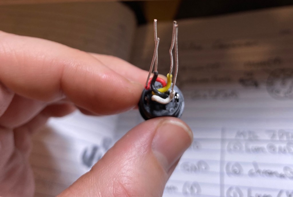
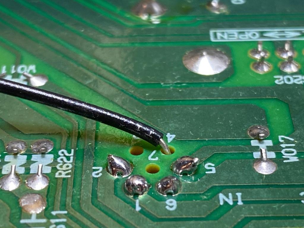
Below is a picture of the soldered connector, and the connector after I stripped the wires and bent them into shape to fit into the original through holes. Solid core is stiff and is tough to work with if you’re making it into wiring harnesses, but for this stuff its perfect and its all about preemptively bending it to fit what you need.
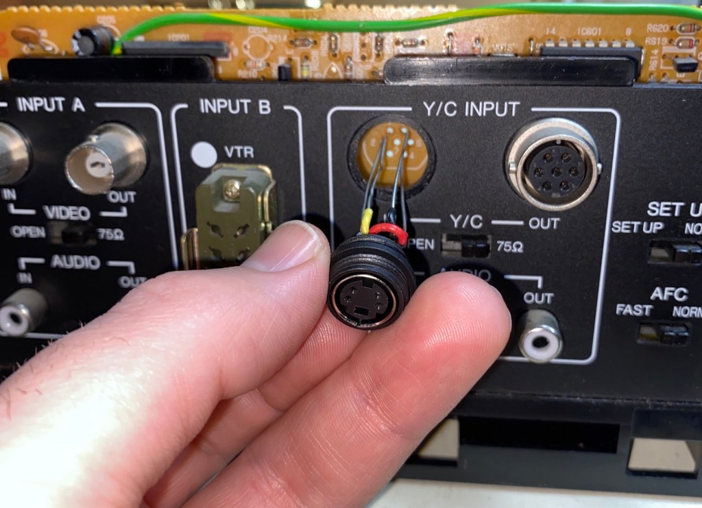
The pinout of the new connector does not line up with the pinout of the old connector, so you have to reroute the wires to line up with the through-holes as shown below. I think it looks pretty cool.
Make sure you feed the nut onto the wires between the panel and the PCB, and fix that before you solder the wires.

Once the connector is soldered on, I soldered the shield to a pin on the PCB already soldered to the panel shields. I did it this way to be fancy, but you can just solder it on the connector first and route it around the top of the PCB to the backside as well.
The difference between ground and shield is sometimes subtle, but sometimes important. So it’s best to assume they are different and find a pin that is technically shield, instead of 0V or GND. When connecting a shield, sometimes a connectors shield IS ground too and that’s a different story. They are usually connected either way, but not being careful with this can cause things like ground loops. If you are into electronics design and don’t know what ground loops are I would recommend looking them up.
Once the connector is fixed to the panel and the connectors are soldered up and trimmed, remember to install those transistors you removed! Once that’s done, everything should go back together quite smoothly. Double check your ground wires!
The Ramble Again
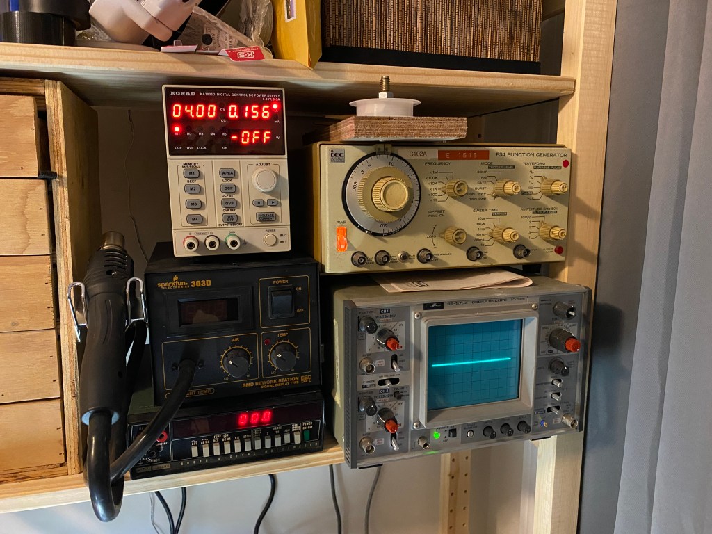
I was pretty excited about this one. I even added my record player to the station and I have it all connected to a pretty awesome sound system. A mostly non-intentional period correct setup I believe. Grant Kirkhope’s work deserves more than a garbage monitor speaker.
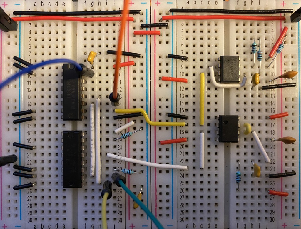
With the purchase of these electronic parts from Digi-Key I also purchased what I need to take another crack at my metronome design. Most of it is operational so I’m hoping to fix up the questionable part of that design soon!


Leave a comment